|
|
Post by lightning on Jan 10, 2019 0:17:07 GMT -9
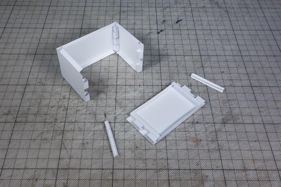
How do you like this approach as an alternate to the "standard" fold flat method? I want to use it for special conditions where I cannot use the regular tabs-help-by-friction approach.
I have written a detailed post on my patreon here.
It has a lot of potential for me, esp if I want to go and make full 3D walls (meaning walls with thickness). It's very easy to design and build.
Let me know what you think about this? Has this been done before? Are there any obvious reasons not to use that?
I will use it for my new Chinese court yard building on the base section (hidden under the floor). But the idea came to me when I was working on my Wild West buildings.
Chris
|
|
|
|
Post by glennwilliams on Jan 10, 2019 8:16:11 GMT -9
Clever design. If we designate the two different end types as A and B, do you plan to have panels with combinations? IE: AA, AB, BA, and BB? I really like the fold over wall top--what a simple, palm slap to the forehead idea. The "post" connector appears to be fairly complex. Would a simple post "box" be easier? If the post were double height, you could easily add a second floor. Round versions of the joiner socket and post would allow for working doors.
This is a very clever design that seems to solve quite a few issues.
|
|
|
|
Post by lightning on Jan 10, 2019 8:32:37 GMT -9
Clever design. If we designate the two different end types as A and B, do you plan to have panels with combinations? IE: AA, AB, BA, and BB? I really like the fold over wall top--what a simple, palm slap to the forehead idea. The "post" connector appears to be fairly complex. Would a simple post "box" be easier? If the post were double height, you could easily add a second floor. Round versions of the joiner socket and post would allow for working doors. This is a very clever design that seems to solve quite a few issues. I haven't thought much about "systemics" yet. I would probably go for the same pattern on each wall panel. So the left side would be the opposite of the right side, so whatever wall I would use it would work.
The post connector is just the tube squashed into the star form. The plain box tube would also work but with this design (it's the same dimensions as the holding parts) I don't need to worry about reducing the side. It reduces itself! And it has this springiness that I like, so it locks itself once inserted. To get it out you need to push it or pull it with a pair of tweasers.
For openable doors and windows you could go as you said. If one wants to build that way esp.
For me the main reason was to make the Wild West "arcades" in front of buildings possible (detachable) and that should work. Will work on that in detail when I start that civ seriously :-)
|
|
|
|
Post by Vermin King on Jan 10, 2019 9:37:48 GMT -9
Judging by the wall laying down, I think you may be boxing yourself into East/West walls and North/South walls. Some will have the boxes at the top on both ends and some will have boxes at the bottoms. If you alternate so that the box is at the top on one side and the bottom on the other, there will be more flexibility by the user on how to connect them together.  Yet by being set up that way, any piece can link to any other piece I think a simple X-shaped locking piece will be easy to manufacture and store. It should lock the walls together efficiently |
|
|
|
Post by lightning on Jan 10, 2019 9:59:47 GMT -9
I see now that my pic was a bad example. What I have described in my reply is excatly what your pic shows Vermin King |
|
|
|
Post by Vermin King on Jan 10, 2019 11:26:34 GMT -9
In the new reality of my life, I find myself 'skimming' more than reading these days. Sorry about that, but doing it this way makes a lot of sense
|
|
|
|
Post by lightning on Jan 12, 2019 6:24:13 GMT -9
In the new reality of my life, I find myself 'skimming' more than reading these days. Sorry about that, but doing it this way makes a lot of sense No problem at all my friend. Just wanted to show we're on the same track of thought  |
|
|
|
Post by Vermin King on Jan 12, 2019 7:05:05 GMT -9
Clever design. If we designate the two different end types as A and B, do you plan to have panels with combinations? IE: AA, AB, BA, and BB? I really like the fold over wall top--what a simple, palm slap to the forehead idea. The "post" connector appears to be fairly complex. Would a simple post "box" be easier? If the post were double height, you could easily add a second floor. Round versions of the joiner socket and post would allow for working doors. This is a very clever design that seems to solve quite a few issues. At work last night (it was slow), I was thinking about the 'round versions' comment. I don't know how many of you have built minimodel.cz vehicles, but their wheels are strips that are wound around a wire or toothpick. Round versions would not have to be wound as tight. That would leave a round hole that could allow toothpicks, or skewers for taller pieces, to connect the walls |
|
|
|
Post by jeffgeorge on Jan 12, 2019 9:49:28 GMT -9
That would leave a round hole that could allow toothpicks, or skewers for taller pieces, to connect the walls I really like the idea of using toothpicks or some other readily available stick as the hinge pin to connect these walls. (And that's what your joints really are: hinges with pins--very clever!) Having to assemble a bunch of posts seems like extra, unnecessary work to make out of paper something that should already be available. The key is just figuring out what is a useful, fairly universal stick of roughly the right size, and adjust the wall thicknesses to suit. Maybe there's a standard-diameter dowel rod that could be cut into short lengths, at least as an alternative to the cardstock posts? (Dowels would have the added minor advantage that they could be poked out of the hinge loops with a pencil point, which everyone has at the table already, instead of having to be plucked out with tweezers, which most folks don't have at the gaming table otherwise.) Also, I wonder how feasible it might be to design wall connections that work in more than one configuration. The example you show seems to work well for 90-degree corners, but will it do straight connections (to create a 2-segment wall), or T- and X-intersection corners? What about zig-zag walls, where one section has an inside corner at one end, and an outside corner at the other? Two-Segment Straight Wall:
----------o----------
T Intersection: X Intersection:
------o------ |
| --------o-------
| |
Zig-Zag:
-------o
|
|
o---------
Maybe the loops could project beyond the ends of the wall segments, to be covered by some sort of sheathe or veneer skinned to look like a corner post? I'm not sure how this would work, but I'd think that having the flexibility to assemble the wall sections into any corner configuration would be a huge advantage over having to assemble half my walls with two corners facing the same way, and the other half with the corners facing opposite ways. And flexibility this becomes more important if you're making walls that have different textures on the two faces--like building walls with different interior and exterior textures. All that being said, you've got a really cool concept here. I'll be very interested to see how it develops. |
|
|
|
Post by lightning on Jan 13, 2019 8:55:26 GMT -9
It will work for "T" (if there is one long wall and another extending in the middle) and corner (90). For 270 one would have to adjust the walls ends to a tooth-like pattern so that the other side can slide through where the "hinge"loops go. For straight (180) also one would need some adaptions. It depends if you only need the outside wall or both sides. Zig-zag is 90 and a 270 corner. So that should work too if outside only. "X" is very interesting. Here I cannot just say I care only for the outside because it's outside everywhere :-) So I will have to look at what changes when I have double sided "thick" walls as a system. For that one might need to incorporate connector parts. mproteau (Paper Realms) gave me a couple of ideas on that one. |
|